Laboratories for urban water management and environmental technology
The well-equipped laboratories offer the opportunity for extensive analysis of the media soil, water and air as well as waste water and waste.
The laboratory offers practical training opportunities in the field of environmental technology at the Department of Civil and Environmental Engineering. This takes place in the practical courses offered and through support in courses in the field of environmental analysis. In addition, students are supported in the laboratories with their doctoral theses, project and experimental laboratory work as well as student research projects and final theses.
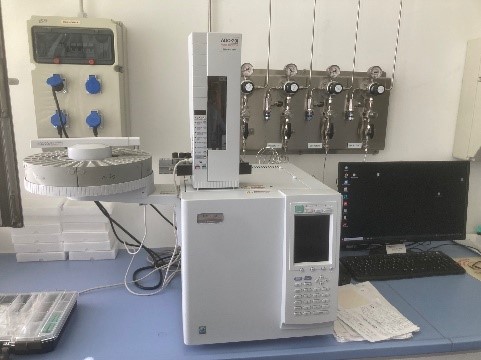
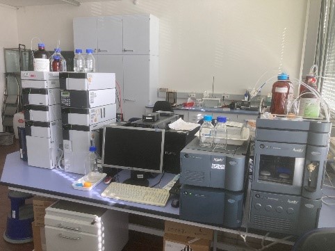
The following list is not exhaustive, but only includes the larger or more important appliances.
- Infrared drying devices
- Measuring devices for oxygen, pH value, conductivity, nitrate, temperature, turbidity, SAK, ...
- UV/VIS photometer
- Flame atomic absorption spectrometer (AAS)
- Gas chromatograph (GC)
- High performance liquid chromatograph (HPLC)
- Digestion systems for total nitrogen and total phosphorus
- Apparatus for the determination of Kjeldahl nitrogen
- Digestion systems for COD determination and equipment for BOD determination
- Transmitted light microscopes (OSB-1) and reflected light microscopes
- Detection and quantification of coliforms / E. coli bacteria (Quanti-Tray Sealer Plus, Colilert-18) and legionella bacteria
- Titrator (TitroLine 6000/7000)
- 2 x 24 h samplers
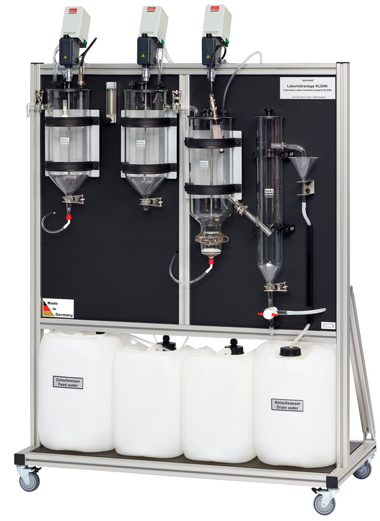
The KLD 4N plant (behr Labor-Technik GmbH, Düsseldorf) consists of an activated sludge plant with a denitrification tank, a nitrification tank with aeration and a secondary clarifier.
The plant is operated with activated sludge and is used in teaching in the water biology and wastewater treatment modules.
Overview:
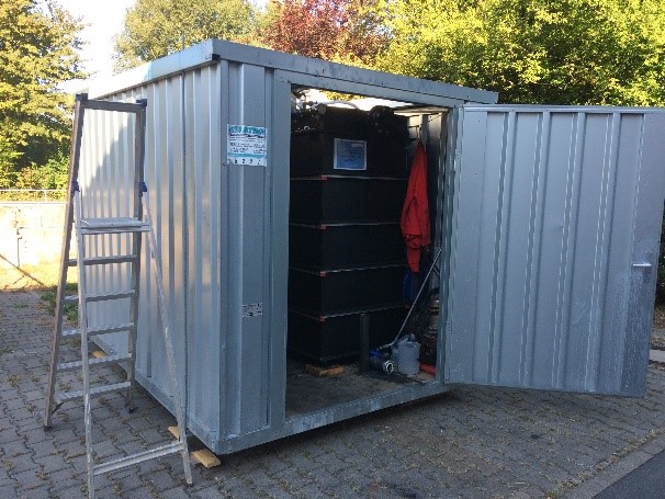
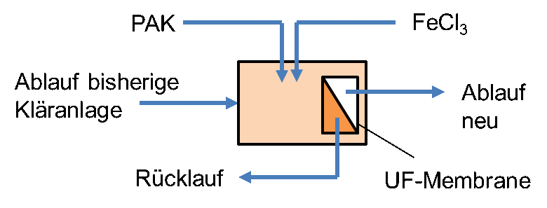
This is a compact container system with a dosing unit for powdered activated carbon (PAC) for adsorption of trace substances and ultrafiltration (UF) for separation of the activated carbon and other solids and bacteria using membrane filtration. It is also possible to add a precipitant (e.g. FeCl3) for further P elimination
Plant description:
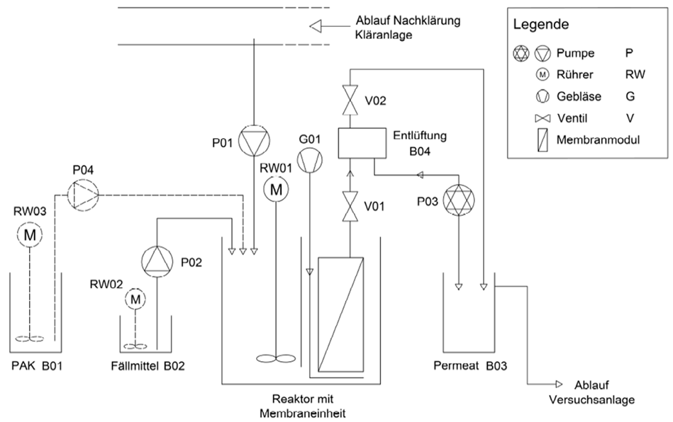
The wastewater from the secondary clarifier effluent is pumped by a level-controlled submersible pump into a reactor containing a submerged UF membrane module and an agitator. The PAH suspension is added to the reactor by a peristaltic pump, whereby the dosing times can be varied depending on the target concentration of the PAH.
The precipitant (e.g. FeCl3) can be added to the reactor under flow control using a diaphragm pump. The membrane module is aerated with a blower and an aeration device installed under the membrane module to achieve a crossflow on the membrane surface.
The treated water (permeate) is pumped through the membrane by means of a permeate pump into the permeate tank, which serves as a reservoir for membrane backwashing. From the permeate tank, the filtrate is returned to the wastewater treatment plant by gravity.
The diagram provides an overview of the test plant. The maximum flow rate is 400 l/h.
Overview:
This system is intended to provide further understanding of process engineering, membrane technology and (waste)water treatment and to give the opportunity to apply these.
In addition, the multi-line design also allows different membrane systems to be compared directly with each other or different operating parameters to be tested in direct comparison.
Plant description:
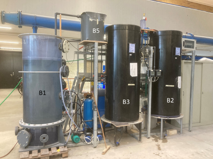
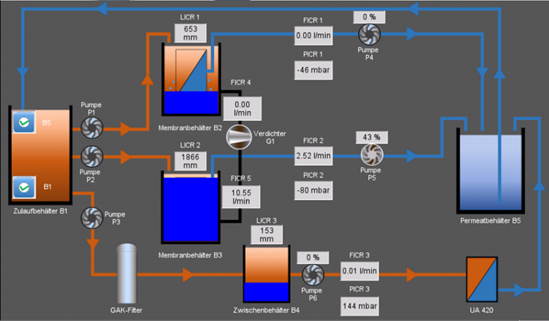
The membrane test plant consists of 3 parallel lines, whereby lines 1 and 2 are identical and line 3 is equipped with a different membrane system.
Streets 1 and 2: submerged membrane system
Road 3: dry membrane system
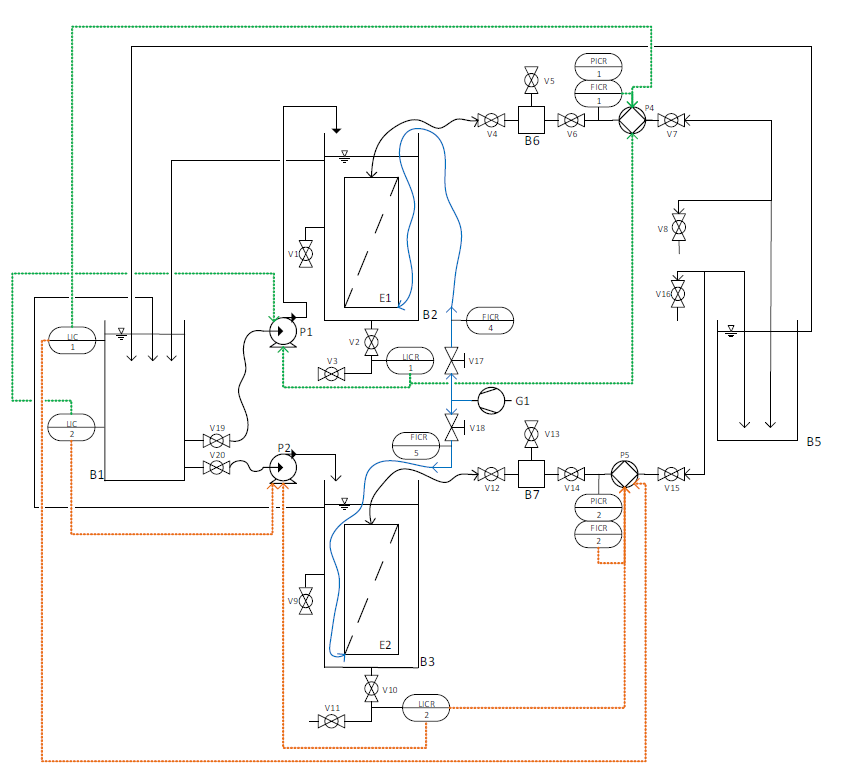
Streets 1 and 2 consist of a common feed tank (feed tank B1), a membrane tank (B2 and B3) and a common permeate tank (B5) from which the water flows back into the feed tank B1.
The water is pumped from the feed tank B1 into the membrane tanks B2 and B3 using pumps P1 and P2. The pumps are controlled fully automatically via the fill level in the membrane tanks.
The submerged membrane modules are located in the membrane tanks B2 and B3. The permeate is sucked through the membrane by pumps P4 and P5 using negative pressure and pumped into the permeate tank B5. Pumps P4 and P5 are controlled fully automatically.
The water flows freely from the permeate tank B5 back into the feed tank B1.
Line 3 consists of an (optional) upstream activated carbon filter (GAK filter for the elimination of trace substances) and a dry installed ultrafiltration membrane.
The test system is controlled fully automatically via a control system.
- Wastewater analysis (physical and chemical parameters) e.g:
- Chemical oxygen demand (COD) and biochemical oxygen demand (BOD)
- Nitrogen: ammonium, nitrite, nitrate, Kjeldahl nitrogen, total nitrogen
- Total and ortho-phosphate
- pH value, redox potential, conductivity, oxygen content, temperature, turbidity
- Analysis of summary effect and substance parameters, e.g. SAK254
- Total dry residue, filtrate dry residue, residue on ignition, settleable and filterable substances
- Detection and quantification of coliforms / E. coli bacteria
- Water analysis (physical and chemical parameters) e.g:
- Acid and base capacity
- Permanganate index, water hardness
- Anion and cation analysis
- Chloride, sulphate, ammonium, nitrate, nitrite, sodium, potassium, calcium, magnesium, lead, iron, copper, zinc
- Concrete aggressiveness
- Colony count
- Waste area
- to be completed
